Page 2 of 2 FirstFirst 12
Results 11 to 20 of 20

Thread: My modelling hobby

  1. #11
    Join Date
    Jan 2013
    Posts
    112

    Re: My modelling hobby

    Hi Thanks for positive replies, after a bad year in 2012 I'm trying to motivate myself back into the swing of modelling, so the positive feedback will hopefully help motivate me back into this

    Yes Col, the most of the models I've scratchbuilt, however the class 47 was more of a modification.
    Also, if I buy a kit I will always alter & modify it in some way to make it 'unique' in some way.

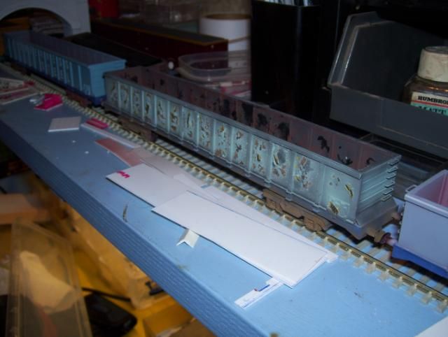
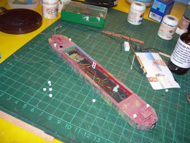
    Here's my scratchbuilt model of a derelict canal butty;


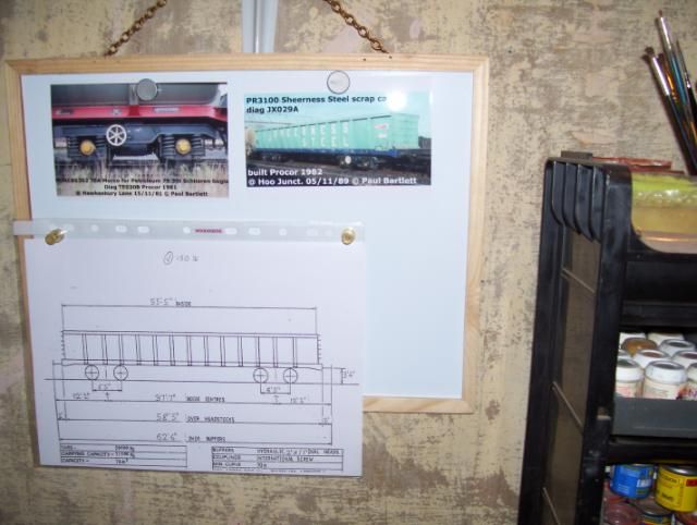
    This project is loosely based on a photos of a barge/butty/boat (not sure exactly what it is, but based on photo's of a "derelict/renovation project" on the BCNS website.
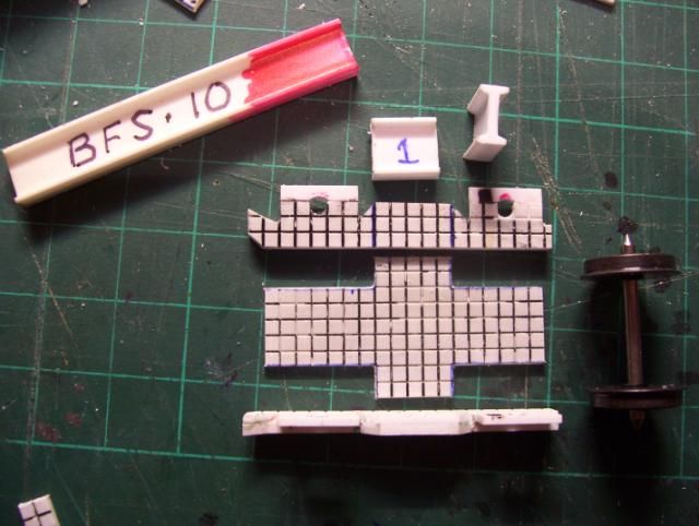
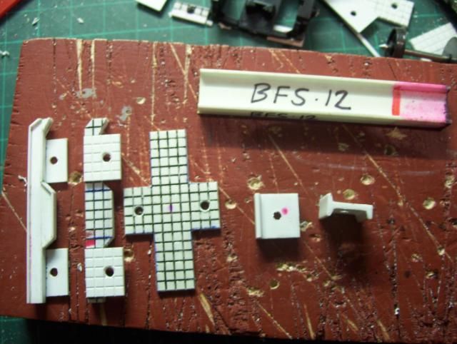
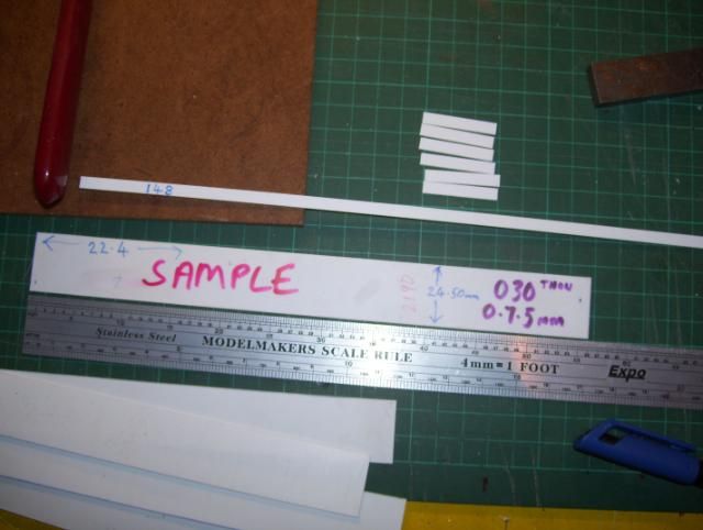
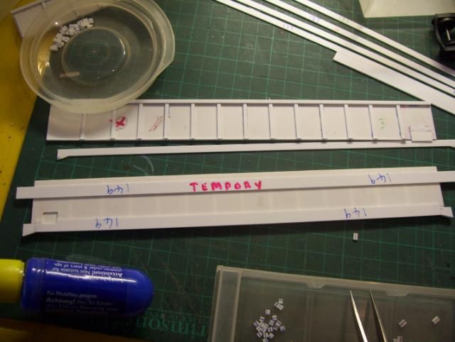
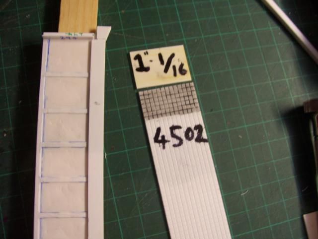
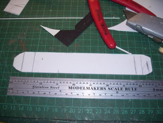
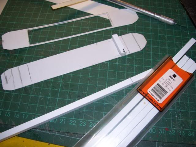
    I decided the boat would be 4mm=ft scale size of to approximately 45ft long x 8ft wide.

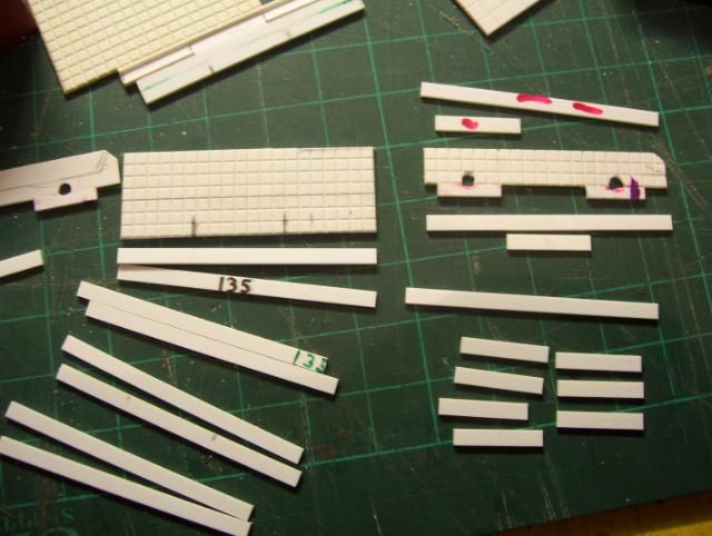
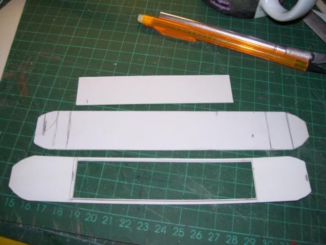
    A duplicate was cut with centre rectangle cut out, at this stage I dont know if I'll be using that as I may use something else, but it gives me a general idea & guide.

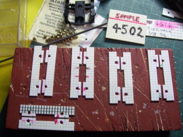
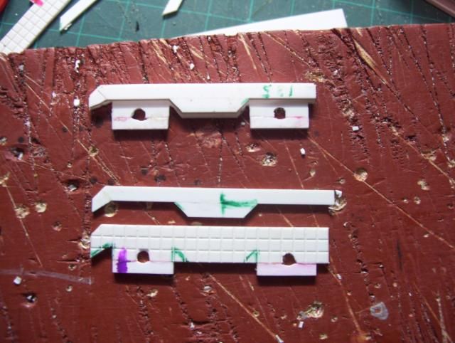
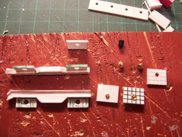
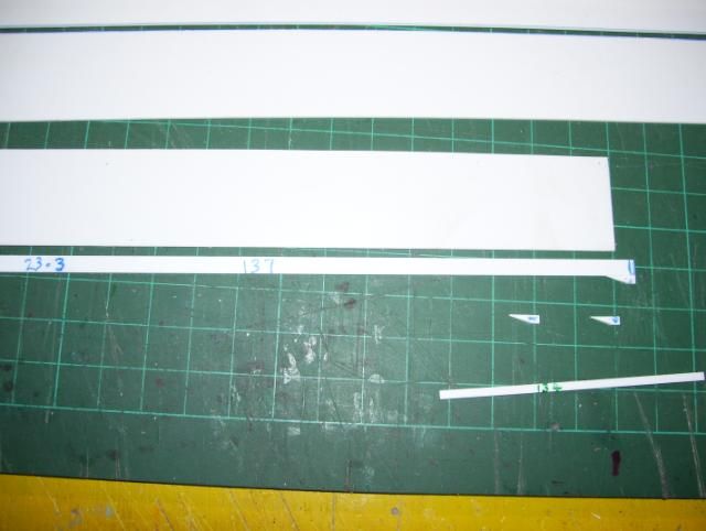
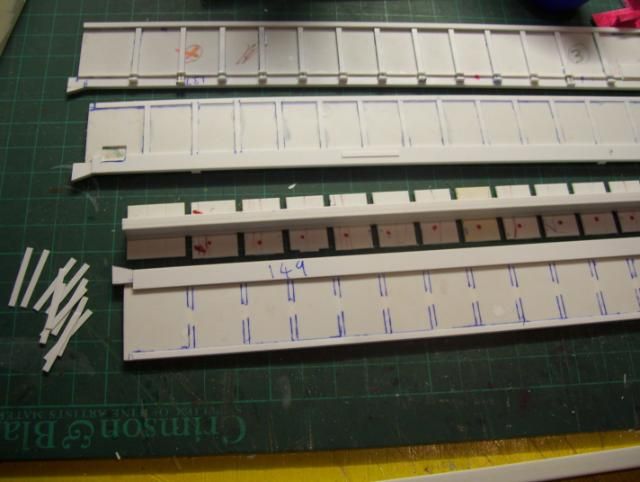
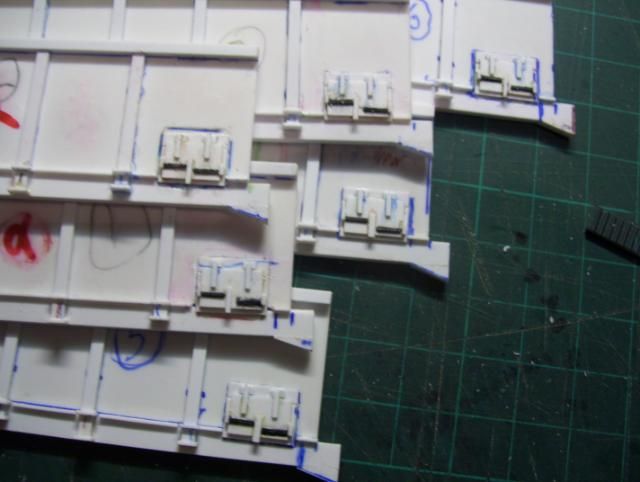
    Using Plastruct #90810 (6.4mm x 6.4mm) I cut & fitted "bulkheads".

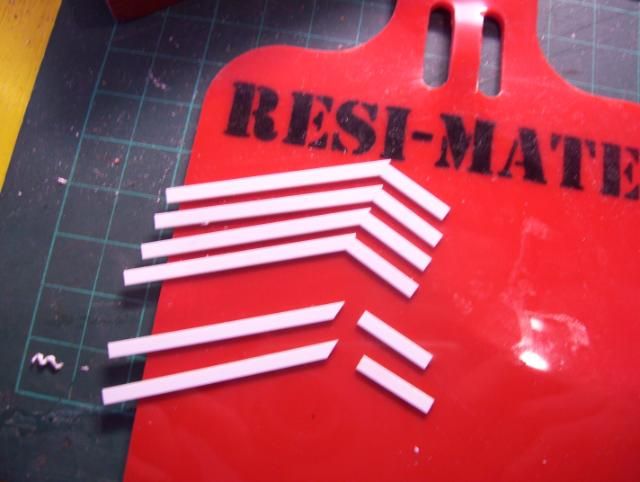
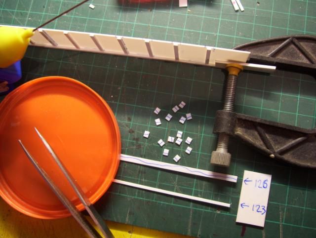
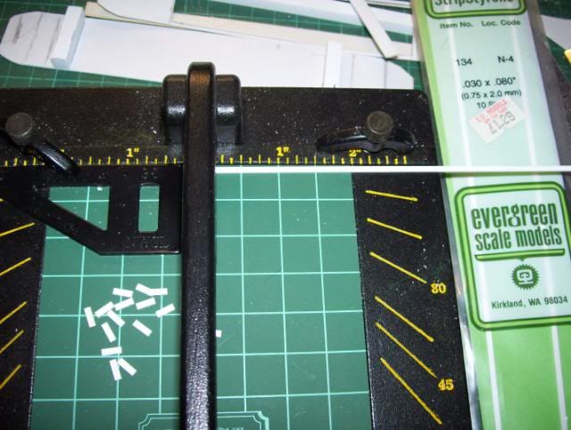
    Using my NWSL chopper, I cut approx 20 Evergreen #134 to 6.4mm length , I'll be using these for stiffeners, as seen on the photo's in link in above post)

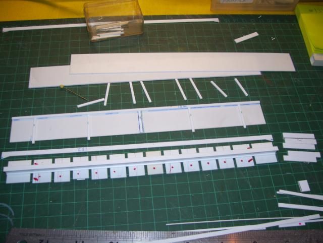
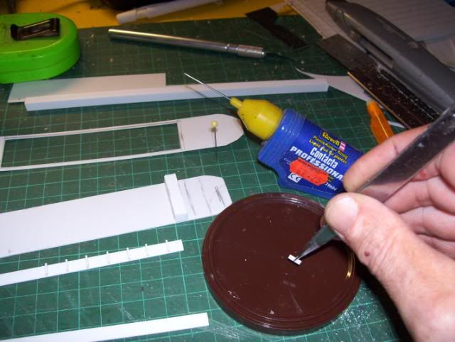
    Using the lid from a gravy granuals container, I made a small pool of Revel Contacta liqiud poly as to use tweezers to dip stiffenner components & position them onto 2 lengths of Plastruct #90749. (1mm x 6.4mm)
    The gravy container lid is nylon or polypropolene (not sure which) but wont be melted by liquid poly solvent, Lids from Pringles tubs can also be used.
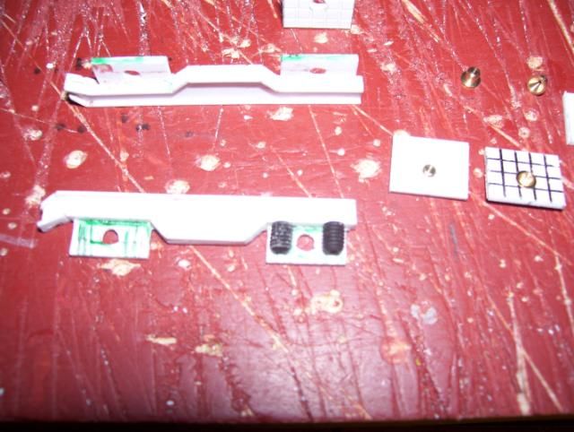
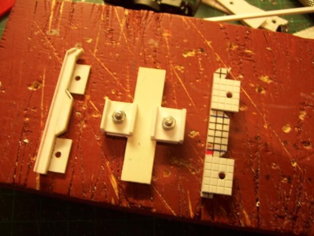
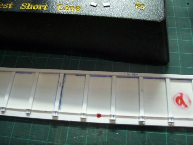
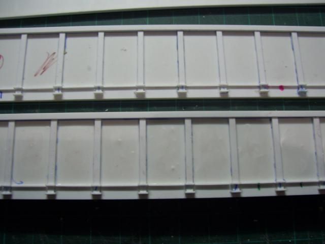
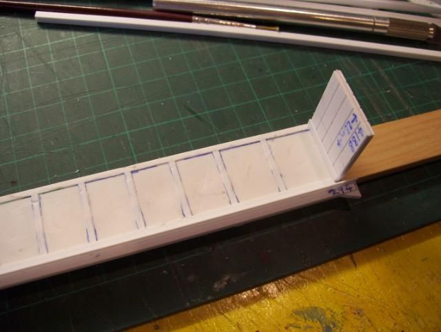
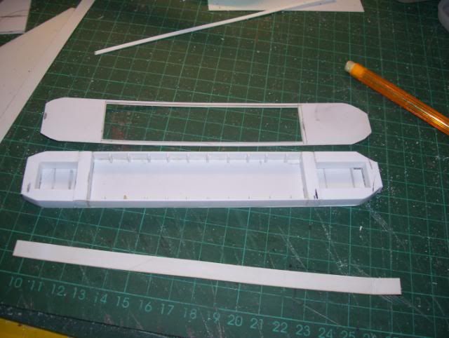
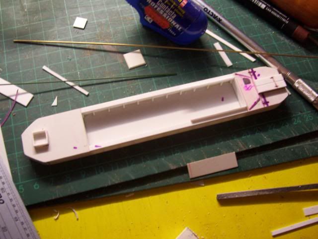
    The re-enforced inner sides now fitted in,

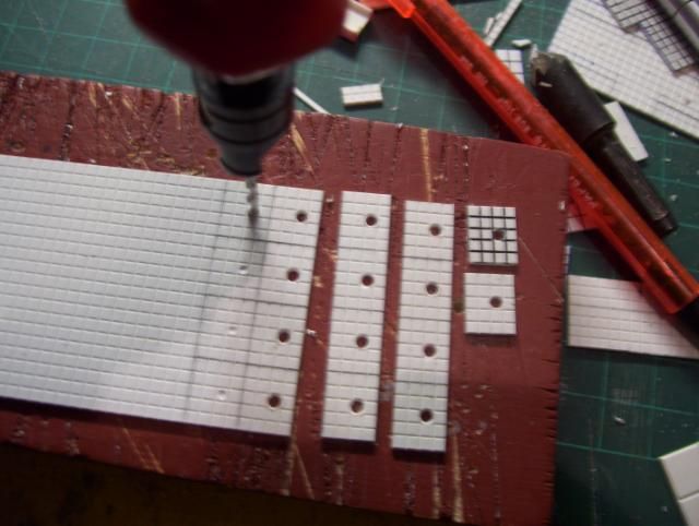
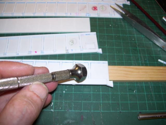
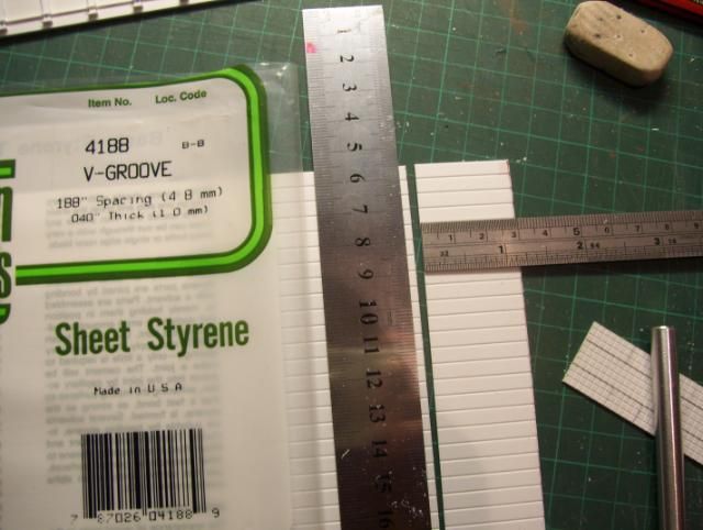
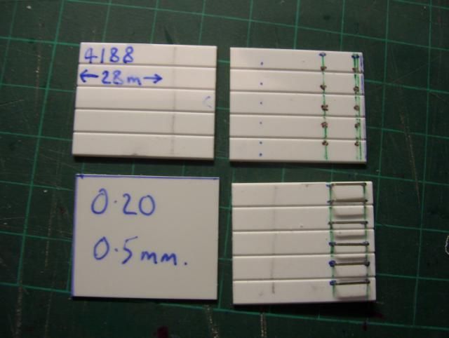
    I cut some 020" plasticard sheet for attaching the outer skin, but firstly, I needed to round those corners off so plasticard outer skin can go around slight curves.

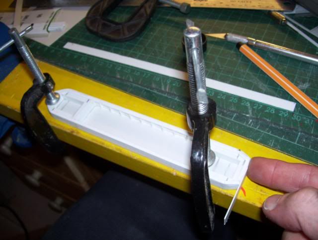
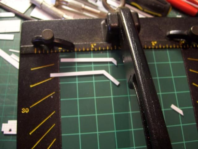
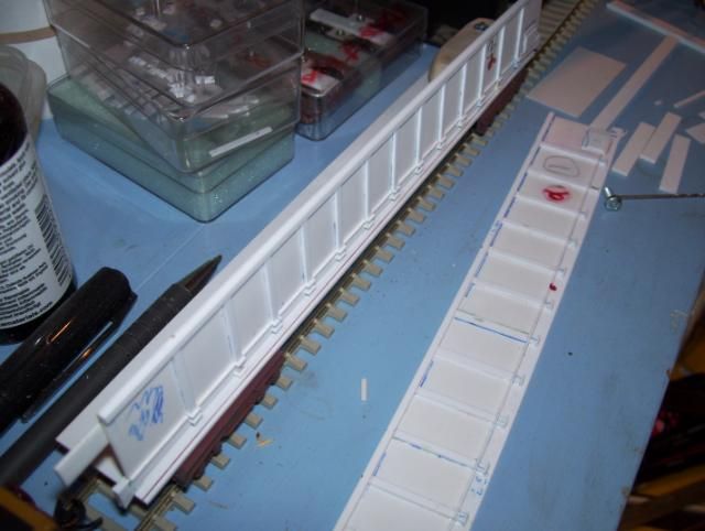
    I've noticed styrene has a tendency to bow & warp over time after poly solvents are used to weld various assemblies together.
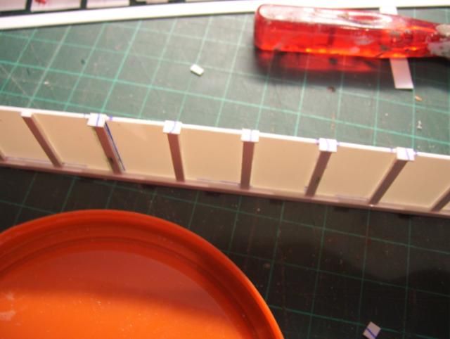
    So I'm using my clamps to hold each end down to the surface of my level workbench & with the clamps holding the boat steady, it also allows me to use both my hands to attatch the outer skin, when it came to going around the curves I needed both hands & fingers free to do this.
    The above photo shows I've successfully gone around the curves of tapered end, I'm counting up to 30 seconds with my finger pressed on where I've applied Revel Contacta.

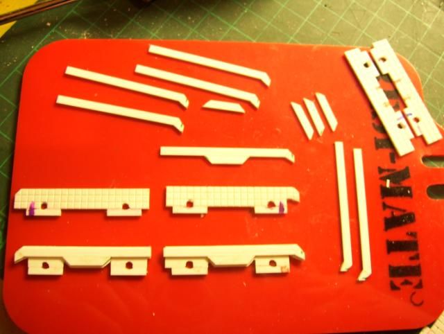
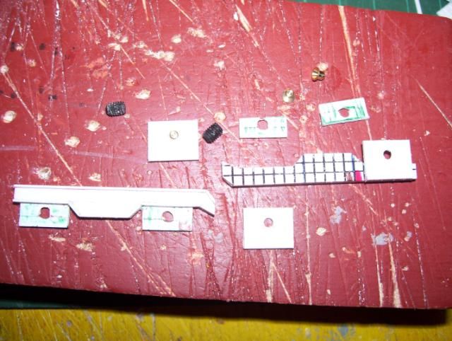
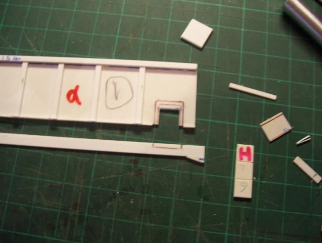
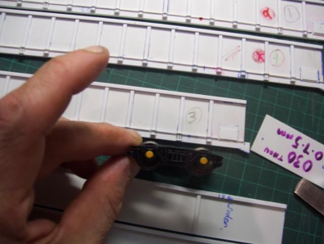
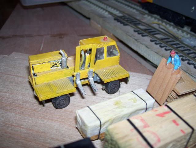
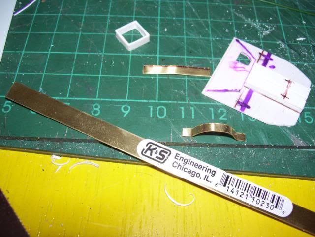
    I cut down some thin brass strip as to make the buffer/gaurd for steering arm etc..,
    then using a small bench vice & fine nose pliers, I bent the component into shape & offered it up for a good fit,

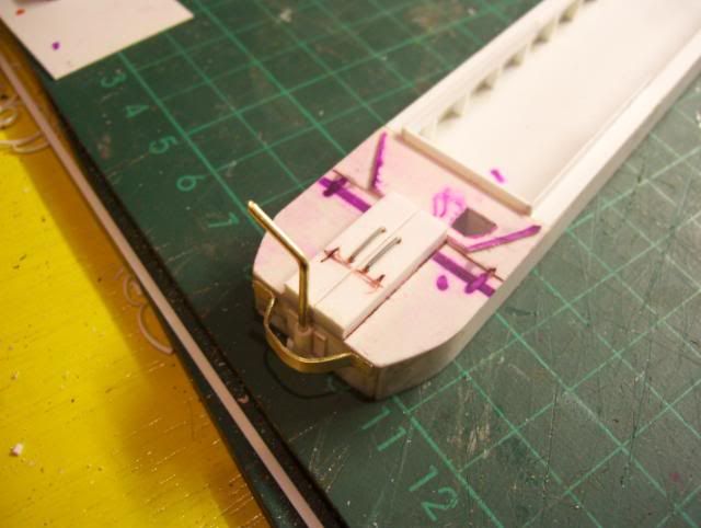
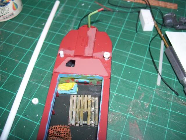
    I started the other end deck detail, as seen above,
    More photo's in a while,

    ---------- Post added at 02:18 ---------- Previous post was at 02:13 ----------

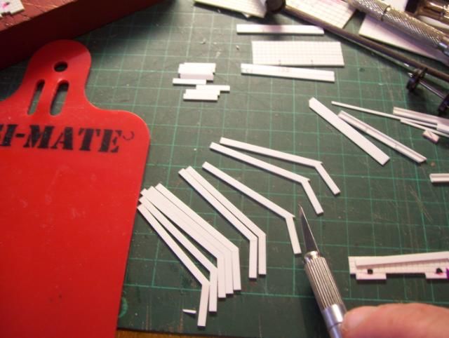
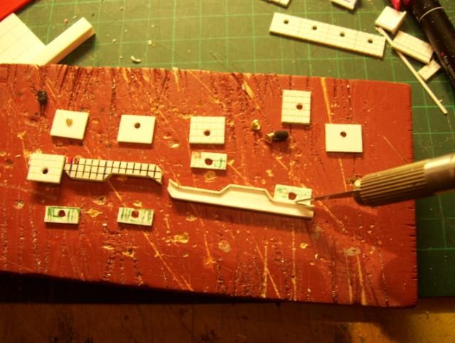
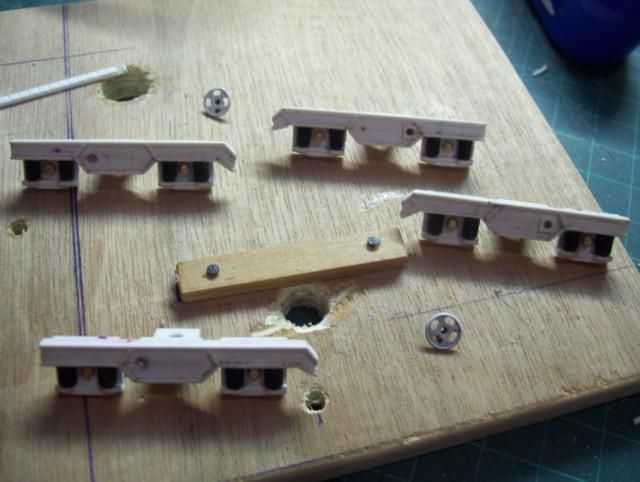
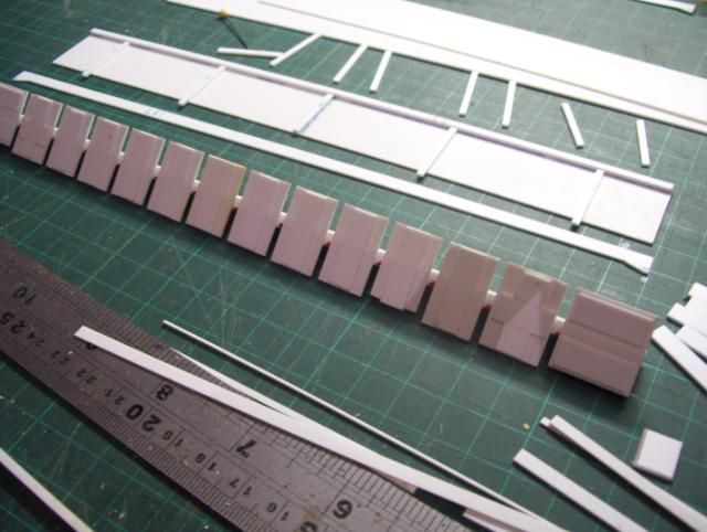
    Continued from my above post, the assembly of componants,


    A close up of detailing to the one end, notice also the slight dent to the gaurd where its taken a bashing, but I'll need to make dent a little more obvious (as based on the real one, as seen in photo's seen from a link I gave in a previous post)
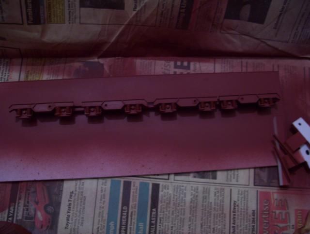
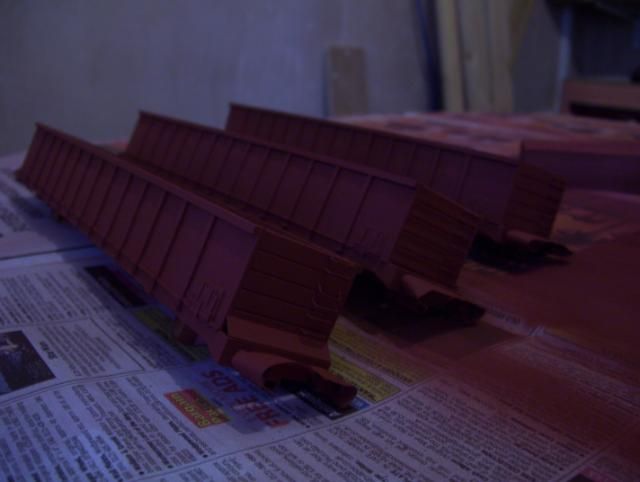
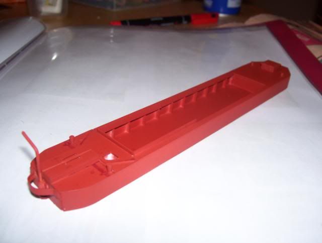
    Sprayed up with Halfords plastic primer (red), it gives an ideal representation of red oxide primer as seen in the photo's in link.

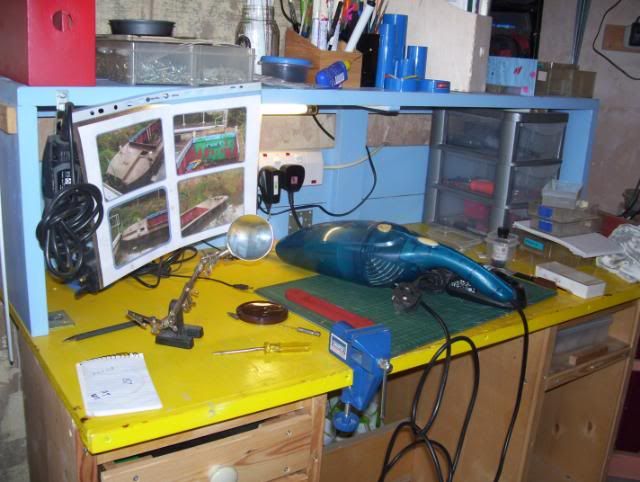
    With the main construction done, it was now time to start painting up, I would'nt describe myself an expert at this, sometimes I learn things as I do them, experimentation etc, so I thought I'd share some of the proven sucessfull basics.

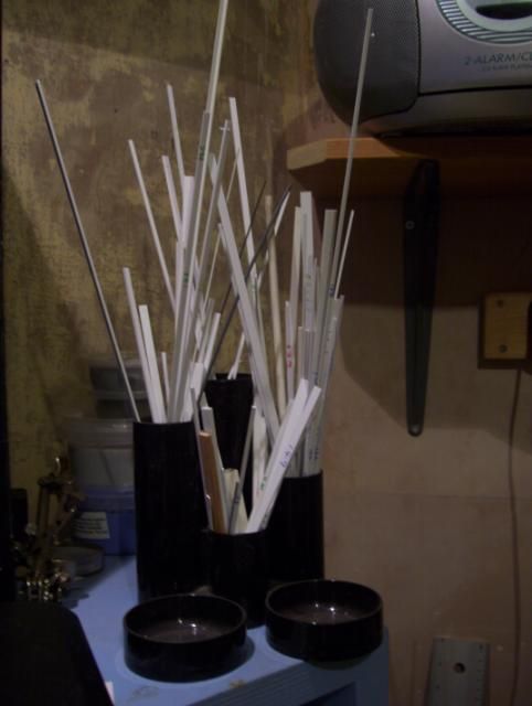
    With all the main boat construction complete, it was high time I cleared my workbench of scraps of plastic & put away the offcuts I could use again.
    I pinned up my referance photo's in readyness for referance of painting & detailing..,

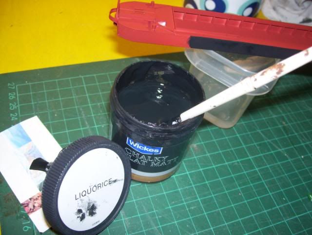
    I started on the outer sides of boat, I wanted to obtain the effect of mattest black possible, various "tester pots" from Wickes DIY stores are ideal for super matt finishes, I used Liquorice in this instance, this matt black will have a topcoat applied of something else in my next update.

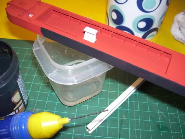
    Whilst handling to paint up various area's , i wanted to avoid handling other areas such as the outside skin, so i fixed a suitable styrene offcut to the floor, it did'nt need be a strong "welded" bond, as, theres a barrier of primer paint, so the styrene was easily removed without damaging the boat floor, there was no need to re-prime it over, as the floor was later painted with a green/black/brown mix of paint.

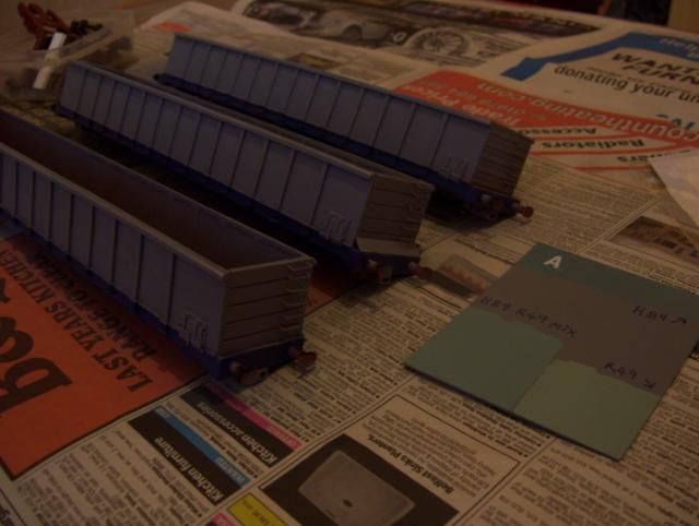
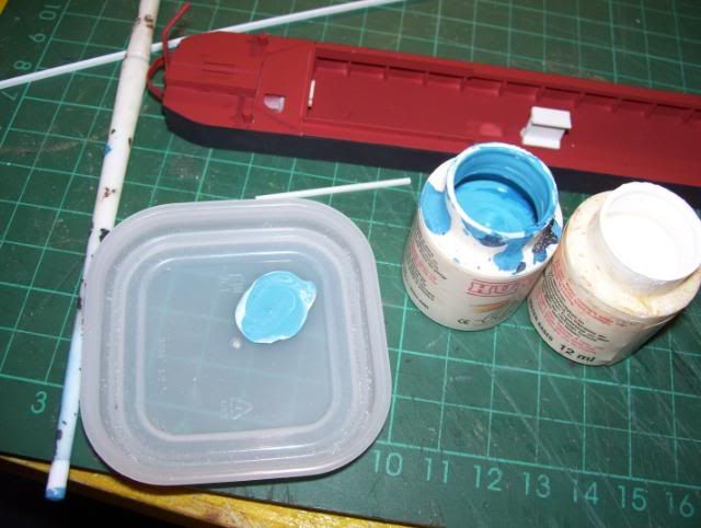
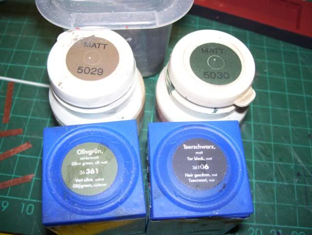
    I've quite a good selection of modelling paints, both acrylic & enamel based, but sometimes I'll need to mix 2 colours as to obtain a certain shade, in this case I needed a lighter shade of blue, so I'm mixing in a little white to medium blue here, both are Humrol acrylics.
    DONT be tempted to mix paints of a different base compound as acrylic , oil/enamel or alcohol* based (*Tamiya) wont mix compatably.

    I used a mix of 4 acrylic paints as to colour the inside floor of boat.

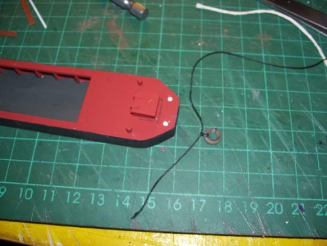
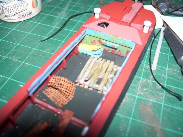
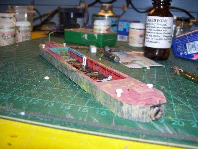
    I decided to add a tyre to act as a bumper, I've used thick strong sewing thread tied to tyre, I've drilled two 1.6mm holes for which the thread will go in to, then sealed in (plugged) with styrene rods.
    I've had to produce my "modellers licence" certificate here, as, the tyre is'nt on the majority of photo's showing boat in poor condition, but a tyre IS fitted on a photo that's after renovation.

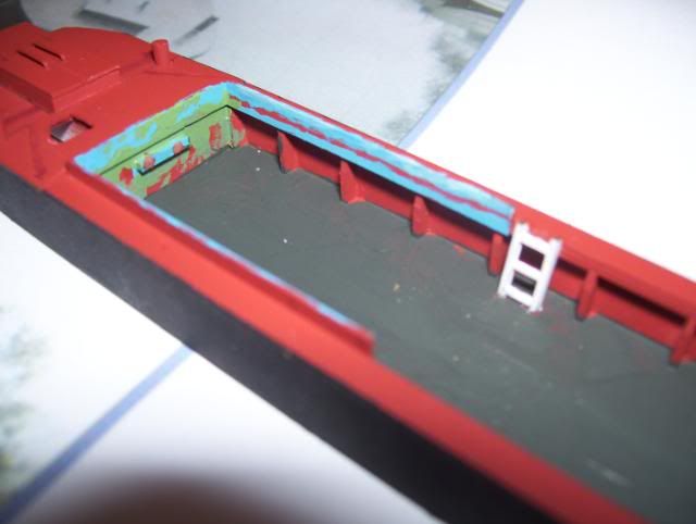
    Here shows paint detailing loosely based on photo's of real boat.
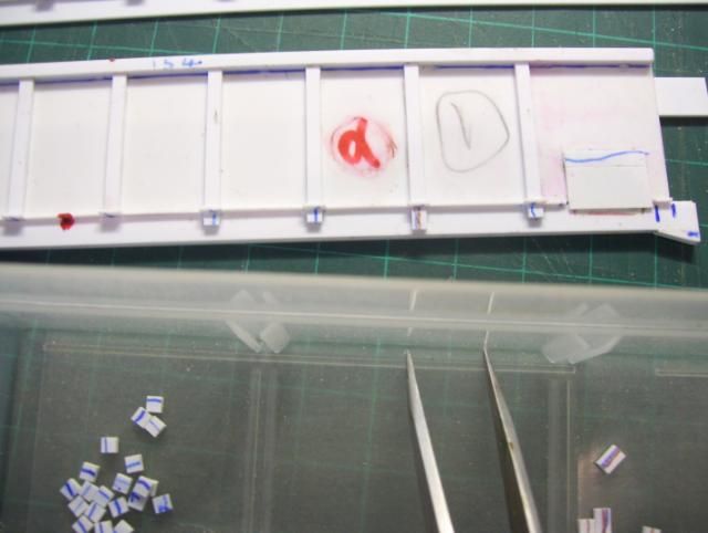
    Portraying a certain level of water inside boat, a ladder was fitted & the boat floor painted, the floor will need a coat of satin varnish applied lastly & allowed to dry overnight, hopefully the varnish I use will not cause the boat structure to warp or react seriously to acrylic paint,
    I used Railmatch varnish (enamel or polyurethane based afaik)

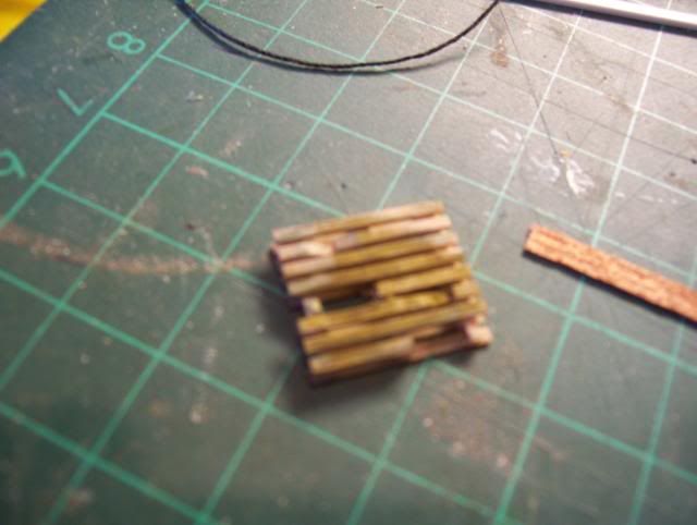
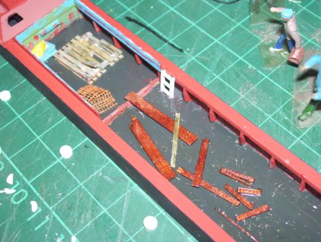
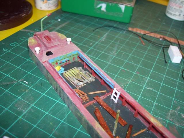
    In a photo of the real one on BCNS link, there's a discarded wooden pallet as well as other junk.
    So for starters, I modified a Peco pallet to portray it weathered & battered,
    My photo here is a little blurred, -I could'nt get a decent close-up shot due to poor light/exposure, but I hope you get the general idea.
    To be concluded..,

    ---------- Post added at 02:22 ---------- Previous post was at 02:18 ----------

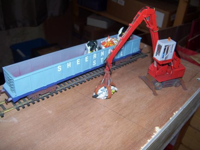
    Next, I gathered some coloured carrier bags, a roll of green cotton mesh, & some crepe paper. These items would be used to make some of the various clutter within boat.

    Here's some of the clutter, 2cm x 2cm sections of carrier bag plastic were cut out & folded twice, with a tiny spot of UHU applied to keep them in folded position, these are to represent folded plastic sheeting as seen in photo's below.
    Also, theres some orange plastic mesh (the sort used for boundary's on building sites & area's of maintemance),
    I decided not to include the sack seen here, but the pallet certainly gets its place as seen in photo's below.

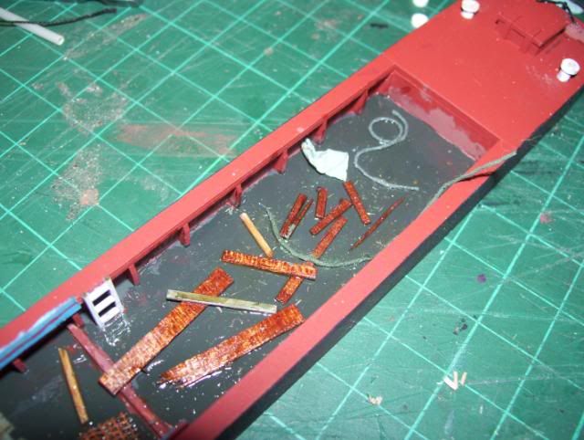
    Now was the time to add finishing touches to the posts/bollards for rope anchorage. I did this using finely chopped pieces of 3.2mm styrene rod from evergreen, these were plastic welded on top of the 2mm posts as shown in this photo.


    The other end of boat, more half submerged clutter was added including - 2 pieces of rope, an untidily folded sheet of tarpaulin, & more broken lengths of timber.

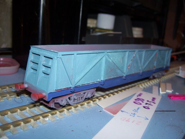
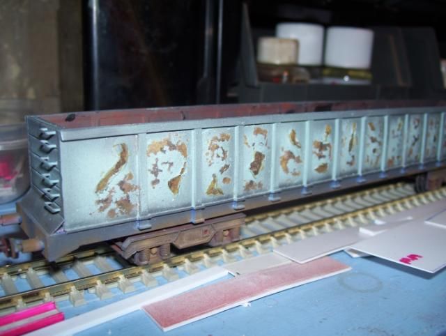
    Using a spare container I made up a mix of peach & white matt acrylic & added approx 40% water, to the sides I chose a brush with flat spread flirted bristles that had gone a little stiff, I applied downward strokes.

    A sprinkling of green weathering powder was applied as to represent moss formation & staining.

    The Boat is now complete made to look in an abandoned negleted condition


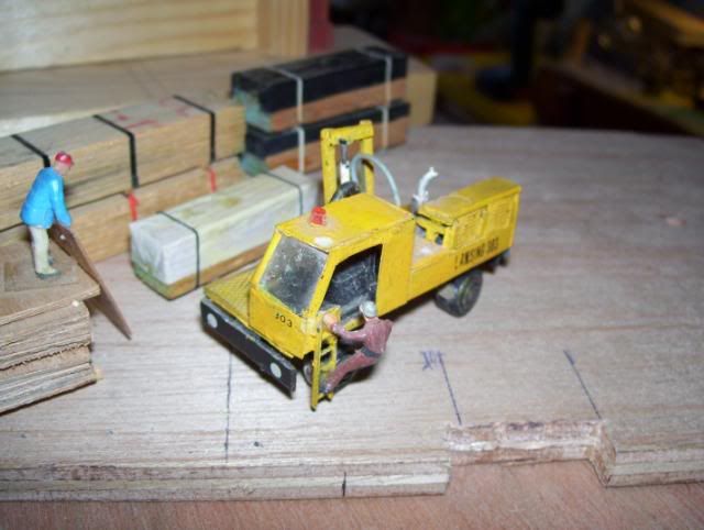
    I will post step-by-step stages on how I scratchbuilt my scrapyard grappler crane in my next post.
    Cheers,
    Dave.
    Last edited by xdavex; 17-01-13 at 03:24. Reason: add info & separate photo's.
    __________________
    Having suspected aspergers , I may sometimes 'appear' to be either abrupt with my posts OR the way I explain things may come across as confusing, so feel free to PM me asking me clarify any of my imput.

  2. #12
    Join Date
    Jul 2010
    Posts
    363

    Re: My modelling hobby

    Wow! these are amazing - well done you!
    __________________
    You can't beat anxiety by fighting it.. only by ignoring it

  3. #13
    Join Date
    Feb 2010
    Posts
    2,352

    Re: My modelling hobby

    Very impressive, I find stuff like this can be good for anxiety as you can just lose yourself in it, and doesn't involve too much brainwork

  4. #14
    Join Date
    Jul 2011
    Posts
    1,131

    Re: My modelling hobby

    Xdavex WOW!!!!!!!

    This is a real skill. To produce a physical picture from your head or from something you've seen , is a serious skill. It's one thing being good at drawing but, producing a 3D model is something else! It involves a bit of a mathematical mind not just art and creativity. Measuring so that everything slots into place, wow! You should enter contests or sell.

    Natural talent.

    ---------- Post added at 18:55 ---------- Previous post was at 18:52 ----------

    Any good at pirate ships????? my little boy would love one.
    Pay u handsomely $$$$$$$$$$$$$$$$$

  5. #15
    Join Date
    Jan 2013
    Posts
    112

    Re: My modelling hobby

    Thanks for positive feedbacks

    Indeed, it does require patience & over the years I've learnt so much about measurements & through researching an item I'm scatchbuilding.
    The items I make are mostly model railway related, but sometimes indirectly railway related, for instance on my first layout I had a scenic feature of a woodyard & sawmills, the real ones have 'sideloaders' for off-loading & stacking of straped timber, my very first scratchbuilt model was a sideloader built purely from my memory from the time I worked in a sawmills. I'll post a pic of my scratchbuilt sideloder in a while.


    Also as part of my current model railway project (a scrapyard dealing with condemned locomotives) , I decided to have a go at scratchbuilding scrapwagons, specifically the long 'gondola' type as used by 'Sheerness Steel'.
    I started with the scratchbuilding of the wagons bogies;

    I studied all my photo's of both the scrapwagon with Scherlian bogies & a close up photo of a Scherlien bogie fitted to a 100 tonne fuel tanker type wagon

    I decided to use Evergreen #4502 embossed sheet styrene, the recessed lines & spaced squares make its so much easier to mark measurements, score & break to precision as required, I've used a boardmarker as to show up the recess more clearly,

    I studied my photos & other information & came to a conclusion for the size of bogie, I'm probably within 2mm give or take- so that 6 inches thereabouts of accurate scale size 4mm=1ft.

    Using Evergreen strip #135, duplicates of 2 sizes were cut to excact duplicate lengths using my NWSL Chopper, angled cuts to lower portion of girder cut after stright cuts had been done,

    cut componants of styrene Evergreen #135 were welded together,

    Excess trimmed off with knife,

    Cut down excess with chopper

    I carefully positioned & fitted them on using tiny spots of Revel Contacta

    I used styrene strip Evergreen #123 (0.5mm x 1.5mm) to follow around the profile of #135 (0.75mm x 2.5mm) as to make odd shape girder design of bogies, applied & complete as seen below;

    Press studs make ideal handbrake wheels, in this case, the 6mm size is especially suited to the scale size and design of wheel that are on some scrapwagons I have photo's showing them fitted with Scherlien bogies,
    I've already started on next stage, I need to be sure certain bogie width & wheel fitment / clearance measurements are correct before I assemble certain areas with plastic weld, commit photos etc,,

    And also I await tiny 3mm dia x 4mm grub screws to arrive from mail order, can anyone guess what I have in mind to use them for if suited ?? - See the photo's below
    I spent time toying the idea of how to construct the top portion of bogies that hold the bogie sideframes together & fit to chassis when required, the top plate shown is one of a few different size plates, its gives a basic idea of what I have in mind, although its still at an experimental stage regarding which size plate to use.

    The Plastruct BFS10 girder profile will play an important part to holding together the bogie sideframes & top,

    I ordered some tiny 3mm x 4mm grub screws from ebay, I used these to represent the coil spring suspension on the bogies

    I reckon the grub screws give a fairly good representation of coil springs, but even after fileing they still prodrude outside of bogie girder, they need to be level with the girder frame flange, so...,

    Due to the grub screw protrudeing too far out from underneath bogie girder, the area's marked green will be removed from each bogie side frame as to allow more recess for "coil springs" (grub screws)

    Duplicate componants were made & 2mm holes drilled in each of them for brass bearings, the marked green area's in photo will be removed & a plate replacing them.

    I removed the area's I've marked with green pen,

    Removeing the last green shaded area. , The new axle holder / backing pieces for coil springs (grub screws) were then fitted onto the rear of #4502 main side frames.
    Achieveing accurate alignment was easy quick & accurate, as the embossed recessed lines gives a natural guide to this, I've highlighted the recessed lines with pen for clarity - I strongly recomend the versatility & usage of the Evergreen embossed card range for this sort of thing- I've used Evergreen sheet #4502 mostly for this project so far.

    For the bracket, I decided to use cut sections of Plastruct BFS12 rather than BFS10, modified them & drilled 2mm holes dead centre of these & the #4502 base plate.

    the bracket & base componant bolted together with M2 x 6mm bolts & nuts. The #4502 base plate itself will be strengthened (to avoid age brittleing and warping) with styrene strip lengthways & crossways.... I get quite obsessive about things I make & I've a habit of over-engineering things like this :roll: all will be revealled later today
    I added more fiddly detail to the bogie side frames & glued those grubscrews in place with "Revel Contacta Special" solution.

    1.5mm holes were drilled into each side frames , the two bogies will have a handbrake wheel on one side of bogie, on the bogie sides that does'nt have a handbrake wheel I've drilled a 1mm hole into a 1.5mm square plate & fitted them on where the option of fitting a handbrake that side would go,

    Bogie side frames & front end frame girders were sprayed up using Halfords red oxide plastic primer, allowing to fully dry overnight ready for painting black / brown / rust.,
    The bogies now completed;


    My next update will show how I started on the bodysides & chassis I made from styrene strip & sheet & 6mm staples, yes 6mm staples !
    Okay.... A sneak preview of whats to come below;

    And also;

    To be continued...
    __________________
    Having suspected aspergers , I may sometimes 'appear' to be either abrupt with my posts OR the way I explain things may come across as confusing, so feel free to PM me asking me clarify any of my imput.

  6. #16
    Join Date
    Oct 2012
    Posts
    2,277

    Re: My modelling hobby

    Very impressive, think they are great.

  7. #17
    Join Date
    Jan 2013
    Posts
    112

    Re: My modelling hobby

    Thanks Alma

    Ok onto the next stage ;
    I built myself 3 of the 'gondola' type scrapwagon below after I decided to complete the other pair of bogies that I'd started , as to enable me to build 2x Sheerness Steel scrapwagons of the same general design (series PR3100 -50) the 3rd wagon having slightly different bogies taken from a fuel tanker & with minor bodyside differences.

    I have a Railway Modeller article about building similar scrapwagons..., the author advises using 0.40 thou thick plasticard for bodysides(1.0mm thick) , but I decided this was too *thick* (*scalewise), so I opted to use 0.30 thou (0.75mm) using 0.30 thou would be easier to create dents, tears & bulges in the "metal" to the slightly thinner styrene sheet, also, I'd estimate the thickness of steel on real examples to be approx 1/2" thick - the 3"x4" vertical brace supports giveing the "main strength" externally, I've used #144 for vertical braceings, the top horizontal bracer is a #154 - as seen on the real examples (Paul Bartlett website & photo's) they're slightly proud of the vertical bracers.

    For the solebar , I used an Evergreen #137 & added some angled pieces for both lower ends,

    The jig I made for spacing of vertical stiffeners, as I'm building more than one scrapwagon of this type they need to be correctly positioned & it also saves time in the long run, especially if I later decided to build a few of them !
    Notice that the 1st & 2nd spaceings for both vehicle ends are wider than those inbetween which are all equal spaceings, as on my spaceing jig.

    The underside view of my jig for spaceing of vertical stiffeners, - notice how I've added 0.4mm thick strip to the bottom with edge clearance - this is to help prevent the jig becomeing un-intentionally stuck when stiffeners are put into place with Revel Contacta (or similar solvent as to weld styrene),

    I used a lightweight G-clamp to hold the bodyside vertically in position as for me to add detailing, (#123 & 126)

    enough Evergreen #126 were chopped to 3mm for the detailing on stiffeners , #123 were cut at 12mm as to fit inbetween each of these, beneath this will be the solebar componant - as seen in other photo,


    I used the lid from a gravy container (or similar) as to create a 'pool' of Revell contacta solvent, picking the tiny cut componants of styrene with tweezers to dip the componants in that needed to be 'plastic welded' to the body.


    At this stage, a cut-out was made for the door/hatch on end of wagon,
    Next,the cut-out will have a backing framework using #124, then a hatch/door will be fitted.
    Various pots & containers were obtained as to store duplicate cuts of many different components,

    Duplicates of evergreen #144 were cut to 2mm, some were cut at 3.5mm , these were welded onto solebar as shown, notice the 2nd bracing thats in-line with the centre of each bogie I've used a #144 cut at 3.5mm.
    A hatch / door backing frame was made using #129 & 124, another #129 will be positioned over this to represent the hatch/door that will be detailed with hinges etc at a later stage using tiny Evergreen microstrips,

    On the reverse side, I lightly tacked a spare #149 , this temporary #149 would be so the whole item would be kept flat whilst I worked upon the outer lower sides.
    Notice that Ive made a small cut- out of the #149 at the hatch/door areas of each side panel, - pointless having a door / hatch the other side if cut-out ins'nt included !
    So, as to re-iterate, solebar is #137 (0.30 thou thickness/ 0.75mm x 4.0mm), the backing for this is a #149 (1.0mm x 6.3mm) as to enable joining reverse of solebar to reverse of bottom bodyside, also re-enforceing the angled area, the #149 cut short 6.3mm each end of length of solebar, so the 6.3 pieces needed can go vertically so it goes over the angled piece & join for maximum strength, trim the angle of #149 to suit the same as solebar profile when fully dry.

    More duplicates of Evergreen #126 was cut on my Chopper, this time at 2mm for the lower most of #144 verticle braceings on the solebar seen here,

    The sides & ends of the wagons will fit on the outside of the floor/chassis, this here is position just to give me an idea of what it'll look like,

    The height of the wagon sides at approx 10'6" seemed to look right positioned next to a Bachmann MBA ,
    To be continued...

    ---------- Post added at 23:35 ---------- Previous post was at 23:24 ----------

    Onto next stage;

    I decided to start on my 3rd body, but this body having different bogies fitted , as seen on Paul Bartletts photo website, a few of these type of scrapwagons had other bogies fitted to them, the bogie seen here to be fitted to my 3rd body is salvaged off a Bachmann TEA 100 tonne fuel tanker.

    Looking at one of my Paul Bartlett photos showing the innerside of one of these "well used" wagons, So I decided to try to add some extra detailing to represent this, I have used thinnest Evergreen strip 0.25mm; Evergreen #104 (thats 0.25mm x 2.0mm, the 2mm being equal width to external braceing #144) were applied internally to area's of top & vertical braceings

    Using a variety of both blunt & semi-sharp objects & a suitably sized piece of wood to rest on all #144 external verticle siffeners & to fit inbetween outside top brace & solebar area (clearance needed to avoid damage to detailing on solebar), I pressed the areas inbetween the innerside stiffeners.,
    Of course, on the real examples there are no internal braceings , but over a period of time & bashed usage, the panels get pushed outward to resemble this effect, I need to take the edges off the #104 internals with a dremel sanding drum or similar as to blend them in appear as the inner sheet panelling.

    Above photo; You can just see the subtle denting & outward bulgeing areas inbetween outer stiffeners,
    Just to add a small tip for fellow scratchbuilders; - an ideal storage pot for storeing items of strip & profile & cutdown sections of them; is a desktop organizer bought from somewhere like Staples or other stationary suppliers, you may have noticed I've marked each of strips I use including offcuts for easy identification & referance, I use fine tip permanant marker pens made by Swann Stabilo, also available from Staples & other stationary retailers.

    Btw, I just thought I'd mention; - I hope my "shows you how" posts are clear & concise , you'll notice I'll use both imperial & metric measurements, but I've a good reason for this; for me , its much easier to read for instance the imperial measurement of 1" 1/16" than its 27mm equivalent in metric millimetres etc, in some cases it'll be the metric thats more easy to read as a "round measurement" or easily identifiable marking on steel rule or tape measure - hence me using eever or ivor - makes perfect sense :lol: .
    Anyway,

    Door/hatch panels were made & hinges, lever & locking bolt details added using fine microstrip & rod - the black rods representing bolts are from some spare spear fence uprights (Ratio models) , as, at the time I never had any rod that was thin enough, ...
    -
    ...although I do have some Evergreen #119 now after my trip to the Modellers Mecca somewhere within the "Bermuda triangle" (A.K.A; Kingswinford & the south west of Dudley region from Stourbridge to Wombourne, Dudley central, Netherton, Sedgeley, etc - I'm convinced Russels hall hospital to be the epicentre / main reason for this strange phenomemen !!! :? :lol: )

    I decided to use Evergreen "V-groove" #4188 for rear panels, the spaceing between grooves suited well , and was preferable to my original plan to make rear panel up of styrene strip - as the nominal sizes were 4.8mm & 6.3mm - I needed a size in between these sizes (approx 5.2mm) - so me using the #4188 was the easiest & quickest option that resembled the rear ends of real PR31xx examples.

    End panels made, 2.5mm thickness in total ; the sections of #4188 were cut to 28mm wide & I drilled 0.5mm holes to spacing as shown, then a 0.20 thou (0.5mm thick sheet of plasticard cut to same size was welded to rear of #4188, then re-drilled as to give extra insertion depth for ladder rungs, I've used type #25 staples for the rungs.
    A backing of another #4188 was welded to these.

    Evergreen #294 (3.2mm 'L' profile) was plastic welded vertically to the end, this was to help gain exact position of the rear panel & keep it rigid.
    The #4502 "tile" is to be the floor of wagon , measured & cut at a width of 1"1/16" it will rest upon the outer profile of #294 fitted to inner side of solebar as shown below, the tile face will be underside as the lines of recess/grooves will help position underside cross braceings that will be matched in line with the bodysides vertical stiffeners.

    Evergreen #294 (3.2mm 'L' profile) was plastic welded onto the inside of solebar, - The floor of wagon (#4502) will be plastic welded upon the #294's, underside cross bracers will be beneath floor, fitted innerside profile of #294's / solebars,.
    - to be concluded...
    Last edited by xdavex; 17-01-13 at 23:30.
    __________________
    Having suspected aspergers , I may sometimes 'appear' to be either abrupt with my posts OR the way I explain things may come across as confusing, so feel free to PM me asking me clarify any of my imput.

  8. #18
    Join Date
    Dec 2012
    Posts
    543

    Re: My modelling hobby

    Xdavex these are amazing. You're really talented! Thanks for posting love stuff like this.
    __________________
    Anxiety.........you have been selected for termination

  9. #19
    Join Date
    Jan 2013
    Posts
    112

    Re: My modelling hobby

    Thanks Arnie, I find the compliments boost my self esteem as to hopefully get myself back into the 'full swing' of modelling after having a traumatic 2012 which depleted my motivation to do anything, so the comments are really apreciated & my step-by-step style of posting may hopefully inspire others to take up what I feel is a very self rewarding hobby

    I should point out at this stage to everyone ;, sorry I Don't build models for others - just for my own personal project, even if I did, its against forum rules to do so for financial gain, so my imput is to gain both compliments & critisism (I can take constructive critisism ) from others on my hobby & to also inspire others to maybe do something similar.

    Okay, continued from my previous post, onto painting;

    I added the ladder rungs - notice some rungs are bent (middle wagon) which is intentional as based on photo's of real examples.

    I primed the bodies firstly with Halfords Dark red plastic primer as to cover my pen markings,
    When dry I applied Halfords grey plastic primer as its more freindly with the shades of blue paint to be applied

    Using a fine brush I started painting the solebars, The colour I've used is Humbrol 25 which I think is a very good match judgeing by my photo's of these wagons from Paul Bartlett.
    It was only after I had painted the solebars that i relized I'd ommitted the feature of adding a chamfer to the topmost of horizontal body stiffeners, so useing a large file I added chamfers , then masked the blue painted solebars for re-applying grey spray primer to chamfers.
    then a brushed on topcoat of Humbrol blue enamel paint

    I applied 7mm high rubdown letters ; "SHEERNESS STEEL"


    One of these wagons (probably the nearest wagon seen here) will be sent off to a chap I know for the application of severe rusting & peeling paint


    Poseing in a proposed scenic action alongside the grappler crane I built.


    I sent one wagon off to a chappy who specializes in adding rust & peeling paint, here's the result;


    Thanks, my next post will show how I built the other design of scrapwagon with diagonal braceings.
    Dave.
    Last edited by xdavex; 18-01-13 at 12:46. Reason: Add text & another photo to conclude.
    __________________
    Having suspected aspergers , I may sometimes 'appear' to be either abrupt with my posts OR the way I explain things may come across as confusing, so feel free to PM me asking me clarify any of my imput.

  10. #20
    Join Date
    Jan 2013
    Posts
    112

    Re: My modelling hobby


    Well heres me at my modelling desk!

    In previous post in this thread I mentioned one of my first attempts at scratchbuilding a sideloader 20 years ago, i've now managed to locate the photo I have of that model I made (above & below)

    Not bad for a 1st attempt at scratchbuilding based on memories of the real example at the sawmills I once worked at

    The 'packs' of wood I scratchbuilt too as to do this scene as part of my old layout, notice the polythene coverings & strap bandings as like the real examples , I used colored carrier bags & fineline trim tape to replicate this, the wood is balsawood scored with a razor saw & very thin plywood or veneer.
    __________________
    Having suspected aspergers , I may sometimes 'appear' to be either abrupt with my posts OR the way I explain things may come across as confusing, so feel free to PM me asking me clarify any of my imput.

Page 2 of 2 FirstFirst 12

Thread Information

Users Browsing this Thread

There are currently 1 users browsing this thread. (0 members and 1 guests)

Similar Threads

  1. New hobby
    By madstitcher101 in forum General Anxiety / Generalised anxiety disorder (GAD)
    Replies: 1
    Last Post: 03-09-12, 12:02
  2. Getting a hobby - a positive outlet!
    By cathytink3rb3ll in forum Top Tips
    Replies: 12
    Last Post: 18-11-09, 16:01
  3. hobby wants to leave
    By lilly-lou in forum General Anxiety / Generalised anxiety disorder (GAD)
    Replies: 17
    Last Post: 02-09-08, 23:38

Tags for this Thread

Posting Permissions

  • You may not post new threads
  • You may not post replies
  • You may not post attachments
  • You may not edit your posts
  •